Flexible PCB Manufacturing Guide
What Is a Flexible PCB?
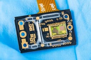
Flexible PCB (Flex PCBs) are designed to bend, fold, or twist without losing electrical connectivity.
They’re made from flexible base materials that allow electronic designs to fit into compact or curved spaces.
This adaptability makes them ideal for portable devices, wearables, and medical instruments.
Table of Contents
ToggleUnlike rigid boards, flexible PCBs can replace multiple wiring assemblies with a single integrated layer.
This not only simplifies assembly but also improves reliability by reducing connection points.
Their flexibility also absorbs mechanical stress, extending product lifespan and performance.

Key Characteristics of Flexible PCBs
Flex PCBs use thin, flexible substrates such as polyimide that can tolerate high heat and movement.
They often feature fine line circuits and lightweight layers to reduce bulk.
Other characteristics include:
High flexibility for folding and rolling applications
Resistance to vibration and mechanical fatigue
Compatibility with both surface-mount and through-hole components
Common Types of Flexible Circuits
The main types of flexible circuits include:
Single-sided flex circuits – simplest form, ideal for low-complexity designs
Double-sided flex circuits – conductors on both sides for higher density
Multilayer flex circuits – multiple conductive layers for complex electronics
Rigid-flex circuits – combine flexible and rigid areas for structural support
Each type suits different applications depending on electrical needs, design complexity, and mechanical stress.
Materials Used in Flexible PCB Manufacturing
Material choice defines a flex PCB’s flexibility, strength, and thermal stability.
Selecting the right base, adhesive, and conductive layer ensures durability and precision during operation.
Polyimide and PET Substrates
Polyimide (PI) is the most common substrate for flexible circuits due to its excellent heat resistance and chemical stability.
It withstands soldering temperatures and repeated bending without cracking.
Polyester (PET) is used for lower-cost or lower-temperature applications where flexibility is still essential.
Conductive Materials and Adhesives
Copper is the standard conductive material because of its high conductivity and formability.
Adhesives like acrylic or epoxy bond the copper layer to the substrate, ensuring durability under stress.
Advanced adhesive-less laminates are also used for high-reliability circuits, improving flexibility and heat tolerance.
Step-by-Step Flexible PCB Manufacturing Process
Manufacturing a flexible PCB involves precise steps to ensure performance, durability, and accuracy.
Circuit Design and Layout
The process begins with CAD design and layout, optimizing trace width, spacing, and bend areas.
Designers plan how circuits will flex and define stress-relief patterns to prevent cracking.
Etching and Lamination
Copper foil is laminated onto the flexible substrate and patterned using photolithography and chemical etching.
After etching, protective overlays or coverlays are applied for insulation and mechanical protection.
Drilling and Plating
Microvias and holes are drilled, then plated with copper to connect circuit layers.
Laser drilling ensures precision for multilayer flex circuits.
Testing and Quality Control
Each board undergoes electrical and mechanical testing to verify conductivity, insulation, and flexibility.
Defective circuits are removed before final assembly to maintain quality standards.
Benefits of Flexible PCB Technology
Flexible PCBs offer numerous design and manufacturing advantages, making them essential for modern devices.
Space and Weight Reduction
Flex circuits replace bulky wiring harnesses, reducing both weight and size.
Their ability to fold or wrap allows compact device designs without sacrificing function.
Durability and Reliability
Because flexible PCBs reduce connector points, they minimize failure risks caused by vibration or shock.
They maintain stable performance under extreme conditions, ideal for aerospace and medical electronics.
Applications of Flexible PCBs
Flex PCBs are used wherever compact, lightweight, and durable connections are needed.
Consumer Electronics
Used in smartphones, cameras, and laptops for connecting components in tight spaces.
Medical Devices
Essential in diagnostic and wearable equipment due to their flexibility and biocompatibility.
Automotive and Aerospace
Ideal for high-reliability systems exposed to vibration, temperature changes, and mechanical stress.
Design Considerations for Flex PCB Manufacturing
Designers must account for bend radius, trace layout, and material selection.
Avoid sharp corners and design stress-relief features to prevent cracking.
Use curved traces instead of angles and distribute bending evenly to enhance longevity.
Challenges in Flexible PCB Production
Flex PCB manufacturing requires precise handling and specialized equipment.
Common challenges include maintaining dimensional stability, controlling layer alignment, and preventing copper cracking.
High initial setup costs can also affect low-volume production runs.
Final Thoughts on Flexible PCB Manufacturing
Flexible PCB manufacturing has transformed electronics by merging compact design with mechanical endurance.
Their adaptability makes them indispensable across industries like medical, automotive, and aerospace.
With proper design and material selection, flexible circuits can deliver long-lasting performance and reliability in the most demanding environments.


